PoKeys DAQ devices family
There are multiple variations of PoKeys DAQ devices (digital acquisition devices) available. The PoKeys57 family consists of PoKeys57U, PoKeys57E and PoKeys57CNC, which is our latest addition to the PoKeys device family.
PoKeys devices in general
PoKeys devices are highly-customizable general purpose I/O devices that extend the I/O capabilities of a host computer in order to interface various signals of the physical world. PoKeys devices can therefore be used to input or output digital signals, analog signals, interface LCD display, encoders, I2C and 1-wire sensors etc. PoKeys devices offer various communication options – USB and/or Ethernet.
Devices can also function as powerful CNC motion controller devices – they can output step and direction signals for driving stepper motors of a CNC machine, while also handling various switches and sensors of a typical machine. Due to a rich set of supported peripherals, one PoKeys device can take care of interfacing the machine and the human operator via switches, selectors, knobs (with encoders), potentiometers, LCD display etc.
PoLabs introduced a programmable logic controller in PoKeys56 family of devices and PoKeys57 family extends this with even more memory and functions.
See highlights of various PoKeys devices below and check the guide on selecting the connection type you need.
The following table gives an overview of many features the PoKeys devices support
| PoKeys57U | PoKeys57E | PoKeys57CNC | |
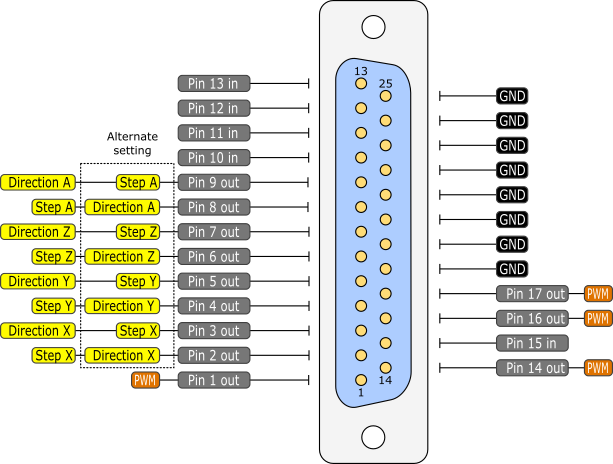
| Number of pins on the board | 55 | 55 | see pinout diagram |
| Digital inputs | 55 | 55 | see pinout diagram |
| Digital outputs | 55 | 55 | see pinout diagram |
| Analog inputs | 7x 12-bit | 7x 12-bit | 5x 12-bit |
| Number of encoders (normal) | up to 25 | up to 25 | up to 14 |
| Number of fast encoders | 3 | 3 | 3 |
| Number of ultra fast encoders | 1 | 1 | 1 |
| Number of PWM outputs | 6 (25 MHz clock) | 6 (25 MHz clock) | 4 (25 MHz clock) |
| Number of digital counters | 24 | 24 | 22 |
| Pulse capture inputs | 3 | 3 | 3 |
| LCD support | Alphanumeric up to 4×20 | Alphanumeric up to 4×20 | Alphanumeric up to 4×20 |
| Matrix keyboard support | Up to 16×8 | Up to 16×8 | Up to 16×8 |
| Matrix LED | Two 8×8 | Two 8×8 | No |
| Keyboard emulation | Yes | No | Yes |
| Joystick emulation | Yes | No | Yes |
| Pulse engine v2 (step/dir motion controller) | Yes (3 axes integrated) | Yes (3 axes integrated) | Yes (dedicated connections for 8 axes) |
| Connectivity | USB | Ethernet (IPv4 + DHCP) | Ethernet (IPv4 + DHCP) and USB |
| Modbus TCP support | No | Yes | Yes |
| I2C sensors | Yes | Yes | Yes |
| 1-wire sensors | Yes | Yes | Yes |
| EasySensors | Yes (up to 100 sensors) | Yes (up to 100 sensors) | Yes (up to 100 sensors) |
| PoExtBus support | up to 10 devices | up to 10 devices | up to 10 devices |
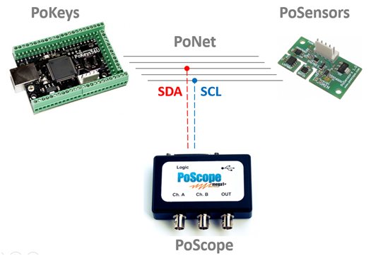
| PoNET bus support | up to 16 devices | up to 16 devices | up to 16 devices |
| Power supply | powered from USB | external 5V power supply | USB for testing,
external 6-26V power supply for full functionality |
| Number of devices per computer | practically unlimited | practically unlimited | practically unlimited |
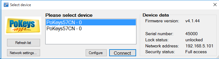
| Automatic device discovery | Yes | Yes (in local network) | Yes (in local network) |
| Free configuration application | Yes | Yes | Yes |
| Free firmware upgrades | Yes | Yes | Yes |
| Communication DLL support | Yes | Yes | Yes |
PoKeys57U

PoKeys57U is a general purpose I/O device that connects to a standard USB port. It provides 55 I/O (5V tolerant) pins, which can individually be configured for digital input or digital output function. Up to 7 pins can be configured as analog inputs and 6 as PWM outputs. The rich set of features includes support for LCD, matrix keyboards, matrix LED displays, encoders, I2C and 1-wire sensors etc.
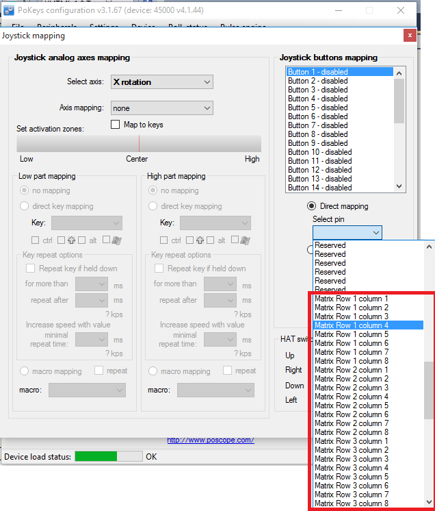
The USB connectivity of the device enables it to emulate a standard USB keyboard and joystick, thus allowing the user to map the digital inputs to USB keyboard or joystick keys, while analog inputs can be mapped to USB joystick axes. Integrated programmable logic controller can be used to enhance the functionality of USB keyboard and/or joystick with custom logic and signal processing (e.g. an interface between R/C PPM servo signals to USB joystick can simply be realized since both are supported by PoKeys57U).
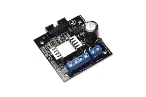
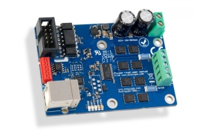
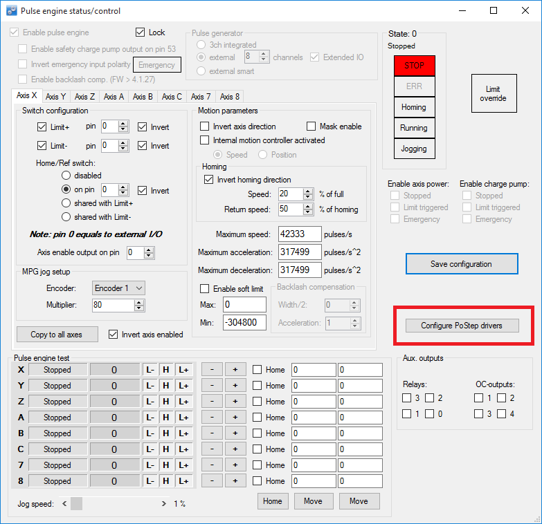
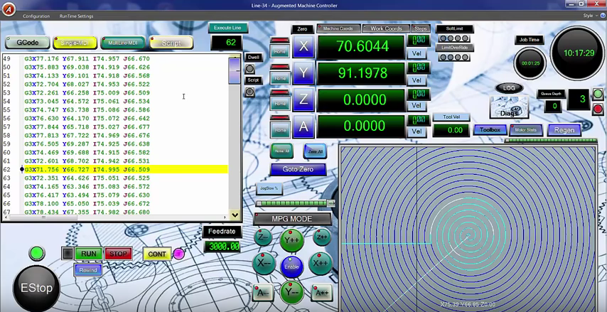
The device by itself can be used as a 3-axis CNC motion controller and can be upgraded to 8-axis with the use of external pulse generator boards.
If you would like to know more about this device, the information is available on the product webpage: PoKeys57U.
PoKeys57E

PoKeys57E is an ethernet version of PoKeys57U device. As PoKeys57U, it provides 55 I/O (5V tolerant) pins, which can individually be configured for digital input or digital output function. Up to 7 pins can be configured as analog inputs and 6 as PWM outputs. The rich set of features includes support for LCD, matrix keyboards, matrix LED displays, encoders, I2C and 1-wire sensors etc.
The PoKeys57E has a built-in web server (named Dashboard) that serves a simplified interface with various (and customizable) values of sensors, digital inputs and outputs, counters etc.
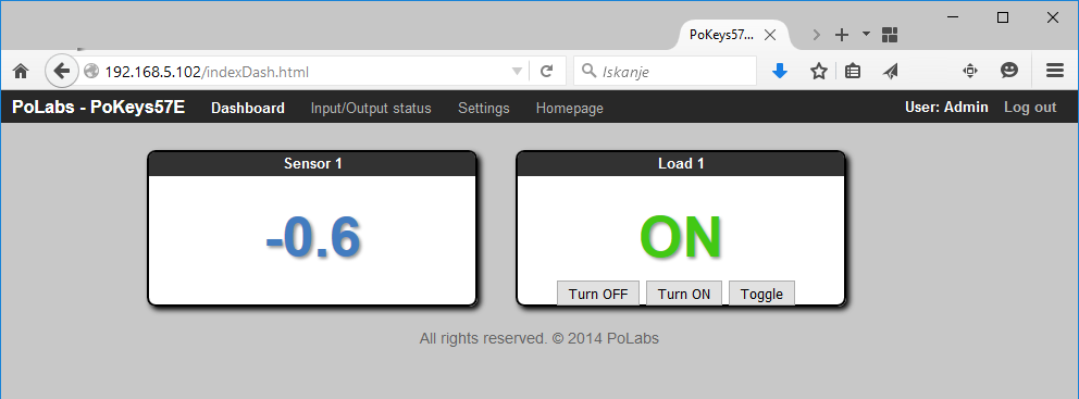
PoKeys57E dashboard
Moreover, PoKeys57E has a built-in Modbus TCP server, allowing it to be interfaced with various industrial equipment. The device also features a server reporting feature, allowing it to upload selected measurement data to a server in a cloud.
As PoKeys57U, the PoKeys57E device by itself can be used as a 3-axis CNC motion controller and can be upgraded to 8-axis with the use of external pulse generator boards.
If you would like to know more about this device, the information is available on the product webpage: PoKeys57E.
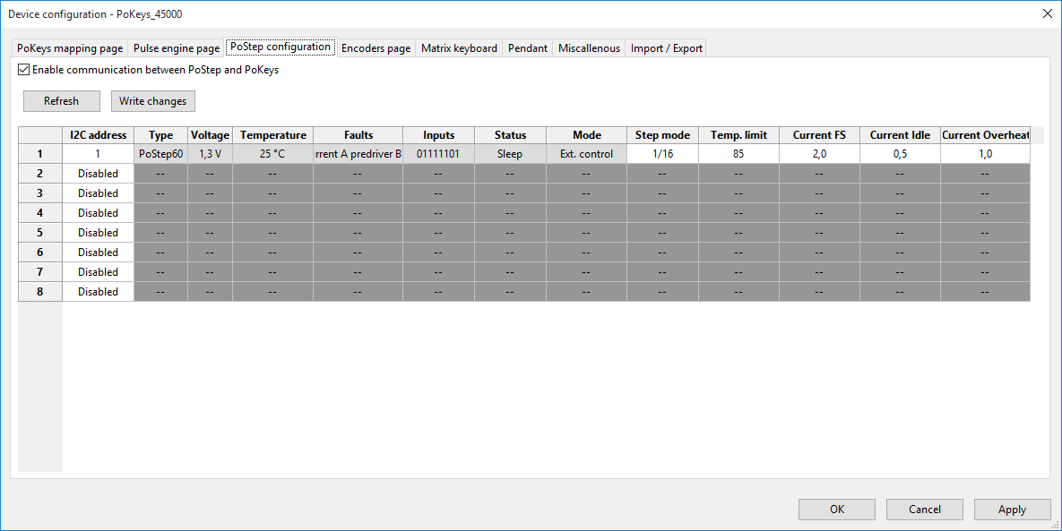
PoKeys57CNC
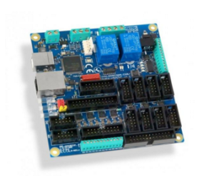
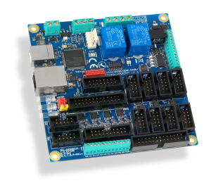 PoKeys57CNC is a PoKeys device that is specialized for the use as the CNC machine motion controller device. The device is designed to be a plug&play solution and hosts dedicated connectors for motor drivers, limit/home switches, pendant, LCD etc. It also has two integrated relays, four galvanically-isolated open-collector outputs and a galvanically isolated 0-10 V analog output.
Layout of the mounting holes, communication connectors and signal connectors allow the device to be installed with ease.
Unlike PoKeys57U and PoKeys57E, the PoKeys57CNC device comes with both USB and ethernet connectivity and the use can select which to use (see chapter below on selecting the connection type).
As is standard in PoKeys57 series devices, PoKeys57CNC device comes with an integrated Programmable Logic Controller – PoKeys57CNC can therefore take care of motion control, user interface and driving auxilary devices, which would normally require dedicated controllers.
More information on this device can be found on its product webpage: PoKeys57CNC.
Selecting connection type
Some PoKeys devices offer both USB and ethernet connections, while others have only one option available. We gathered the following facts to help you choose the connection type when in doubt which one to use:
- Cable length: USB devices are limited to a combined cable length of 5 meters, while ethernet cables are limited to 100 metersin length
- Power supply: USB devices can usually be powered directly from the USB port of the host device, while ethernet devices require an external power supply to function. If the device is connected to multiple loads and peripherals, the power from USB may not be enough and the device will require an additional power supply (as in case of PoKeys57CNC)
- Reliability: both connection types provide high reliability and protection against electrical noise. However, since ethernet devices are galvanically isolated, the odds of ground loops are greatly reduced
- Convenience: since most of computers have built-in USB ports, connecting the PoKeys57CNC to a PC via a USB cable is the most convenient solution. However, this requires that the computer is in close proximity to the machine. On the other hand, ethernet cable can be connected to a standard router and make the PoKeys57CNC device available to any PC in the network
- USB only features: PoKeys57CNC device functions as a virtual USB keyboard and joystick, which can be fully configured by the user (e.g. activating the screen controls via keyboard shortcut)
- Ethernet only feature: PoKeys57CNC device feature a built-in web interface and support for Modbus TCP (Server). Both are accessible to other devices in the network, allowing a remote supervision of sensor values or other parameters. Ethernet PoKeys devices also support server reporting feature for uploading measured data to cloud servers.
The post PoKeys USB and ethernet DAQ devices – comparison appeared first on PoBlog™.