In this blog we will introduce, how we replace an electric motor and setup new components on CNC lathe. All ideas for upgrade CNC lathe spindle motor started with new asset- CNC lathe in company. New machine in our machine shop with intention to improve our suppot even additionally and also with intention that we are making products for our development and needs. If you had problems with installing new 3-phase electric motor and VDF (variable frequency drive) in description you will find out all information for proper setting.
Spindle motor before conversion
With the asset- CNC lathe (Prvomajska Tabturn 100), on machine was installed an electric motor – 1 phase with power 250W and spindle RPM (4500 rpm/min) was extremly high for such type of machine. Electric motor had function ON/ OFF and change direction of rotation spindle CW/CCW.
Clik here to view.

3d Idea for CNC Lathe spindle motor
We decide to replace the electric motor. Upper data (4500 Rpm/min) were base for choice. Spindle on our CNC lathe not made for such high RPM. So we deciede to setup an 3- phase asynhronous electric motor and VFD. The previus motor was 1- phase 250W. We selected 3 – phase electric motor,power: 550W,2-pole – 2740 RPM/min. The choice for the correct type of motor we had two condition: limitation with work place and high power and torque. When motor was chosen, was next step to correct reducing RPM with pulley to make correct ratio. Ratio in our case is 2:1, thats mean pulley on electric motor is 75mm and pulley on spindle is 150mm. Gear ratio 2:1 in our case means 1370 rpm/min on spindle at line frequency 50 Hz. VFD makes possible for us we can manage to reach higher or lower rpm.
Clik here to view.

Setup new components on CNC lathe
Below are main components which we use it for new CNC Lathe spindle motor setup. From 3d model – we can see, there we were also reduced with place at an assembly. Assembly start with fastening of holder of an electric motor. Holder has aligment holes which assist for an easier assembly and corect belt tension when motor is fixed on holder and belt is on pulley then we insure for correct belt tension.
3-phase asynchronous motor
Asynnchronous motor: 2 pole – 2740 rpm/min – 50 Hz, power rating 0,55 kW.
VFD-Variable frequency driver
INVT GD20-0R7G-2S-EU
AC 1 phase 220 V input, AC 3 phase output, power rating 0,75 kW
Inverter Input filter
FLT-PS2010H-B
Inverter input filter. AC 1PH 220V, 50/60 Hz. The inverter input filter is recommended, inverter input filter reduce ripple effects
Clik here to view.

Clik here to view.

Wiring a new components
Below photo – wiring diagram, presents connecting variable frequency drive to electro motor. L/N and ground wires are connected to wire terminal blocks which are mounted in CNC control box. In wiring diagram we can see input filter, variable frequency drive and 3- phase electric motor.
Clik here to view.

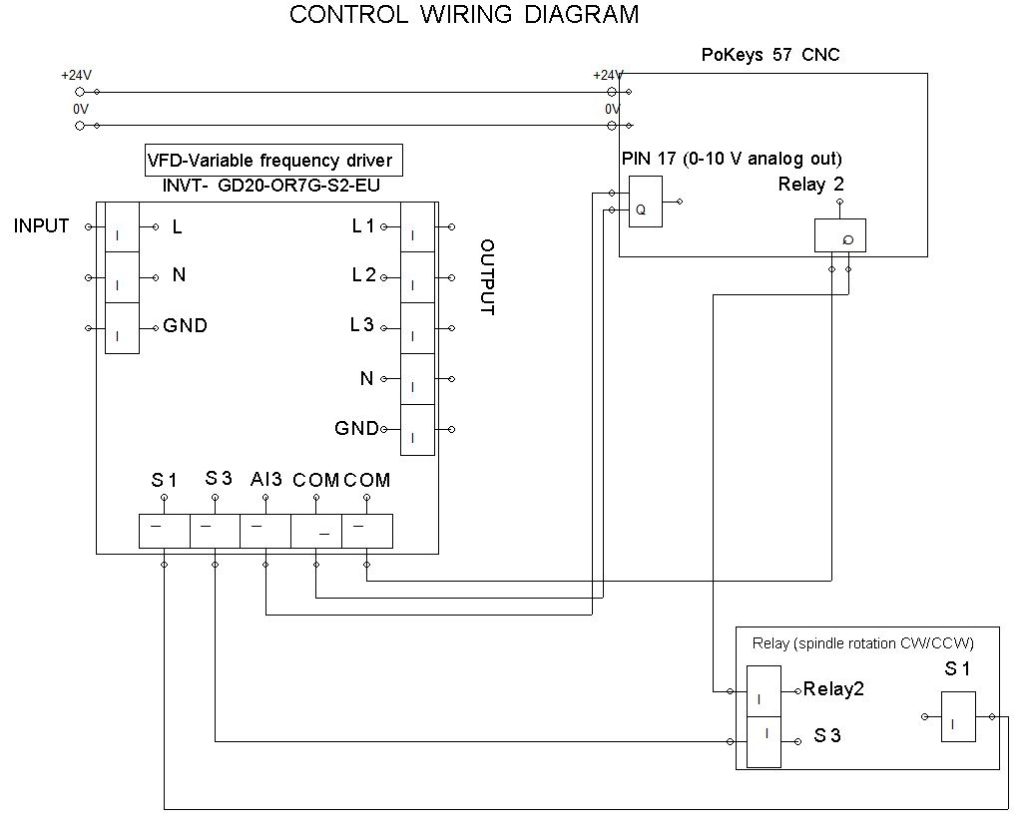
The diagram below – is control wiring diagram. Control wiring dagram include: Variable frequency drive, Pokeys 57 CNC and Relay.
Clik here to view.
Additional information for CNC Lathe spindle motor
Under download find Pokeys 57CNC user manual.
The post CNC Lathe spindle motor – part 1 [Setup & Wiring] appeared first on PoBlog™.