PoRelay8 is a relay board and features 8 relay outputs. Up to 10 boards can be daisy-chained over the CAN bus for up to 80 additional outputs. In previous blog (Using PoRelay8 with PoKeys and long cables) we wrote about connecting PoRelay8 relay board to PoKeys57U device over the PoExtBus. The PoRelay8 is an updated version of PoExtBusRe relay board – see the mentioned blog article on advantages.
But PoRelay8 board can be connected directly to other devices which support communication over I2C protocol. In this blog, we will present an example of connecting single PoRelay8 board directly to Raspberry Pi 3.
In next blog (Part 2) we will add additional PoRelay8 board that will be daisy-chained to first PoRelay8 board with use of a CAN bus and long cables.
Connecting PoRelay8 relay board to Raspberry Pi
I2C is two wire serial communication and requires two pins (and ground) on Raspberry Pi and PoRelay8 board to be connected together.

Picture 1: PoExtBusIn connector as is on PoRelay8 board with marked pins SCL, SDA and GND.
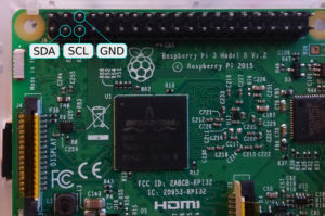
Picture 2: GPIO connector as is on Raspberry Pi 3 Model B with marked pins SCL, SDA and GND.
For everything to work, pins marked SDA on Raspberry Pi and PoRelay8 must be connected together and same is true for pins SCL and GND.
Before powering up your setup, do not forget that PoRelay board requires a separate 12 V or 24 V power supply (depends on relay type on your board, required power supply is marked on PCB next to screw terminals).
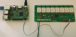
Picture 3: PoRelay8 board connected to Raspberry Pi 3
Enabling I2C on RaspberryPi
I2C bus on Raspberry Pi is disabled by default. It can be enabled with use of raspi-config utility, which is accessed with the following command:
sudo raspi-config
At first screen select option 5 (Interfacing Options) and press enter (picture 4).
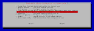
Picture 4: Raspberry Pi configuration
At second screen select option P5 (I2C) and when asked if you want to enable I2C bus, select yes.
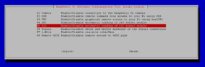
Picture 5: Raspberry Pi Interfacing options
Now you can exit raspi-config utility and reboot your Raspberry Pi with command:
sudo reboot
After reboot, I2C is enabled and ready for use.
Discovering devices connected to I2C bus
Raspberry Pi 3 has two I2C buses, numbered 0 and 1. Bus 0 is used for internal applications and it is not available to user.
Each device connected to same I2C bus must have unique 7-bit (or 10-bit) address. To find out your device address you can use i2cdetect command on your Raspberry Pi. In our case two switches are used, -a which will perform scan over all possible addresses and -y 1 to perform scan on correct I2C bus.
sudo i2cdetect -a -y 1
Output should look something like (addresses are represented in hexadecimal format):
0 1 2 3 4 5 6 7 8 9 a b c d e f
00: 00 — — — — — — — — — — — — — — —
10: — — — — — — — — — — — — — — — —
20: — — — — — — — — — — — — — — — —
30: — — — — — — — — — — — — — — — —
40: — — — — — — — — — — — — — — — —
50: — — — — — — — — — — — — — — — —
60: — — — — — — — — — — — — — — — —
70: — — — — — — — — — — — 7b — — — —
i2cdetect tries to contact every possible address and if device is present, it should reply when its address is called. Address 0x00 is general call address to which all devices should respond and can be used if only one slave device is present on the bus.
As we can see, our PoRelay board has address 0x7b.
Pigpio library installation and configuration
In this example pigpio library is used for communication over i2c protocol. It provides nice python module for communication with pigpio daemon. Python commands reference can be found on library website. Here are short instructions how to install pigpio library on Raspberry Pi 3:
wget abyz.co.uk/rpi/pigpio/pigpio.zip
unzip pigpio.zip
cd PIGPIO
make
sudo make install
After installation start pigpio daemon with command:
sudo pigpiod
To start daemon at boot time, add this command into /etc/rc.local file.
Setting the outputs on PoRelay8 board
Now as we know our PoRelay8 board address and pigpio daemon is running we can use python script to send commands to our relay board as is presented in the following example.
To set PoRelay8 board outputs, 3 bytes of data must be sent to board. First byte is command, which tells PoRelay8 board to turn on or off the outputs. Second byte is actual setting of the outputs, where every bit corresponds to one relay output. Last byte is sum of first and second byte.
Python code example
import pigpio

#Set PoRelay8 board i2c address
DEVICE_ADDRESS = 0x7b

# Connect to Rapberry Pi and open i2c handle to bus 1
pi = pigpio.pi()
bus1 = pi.i2c_open(1, DEVICE_ADDRESS)

# Set Porelay outputs
command = 0x20
outputs = 0x55
checksum = (command + outputs) & 0xFF

request = [ command, outputs, checksum ]

# Send to PoRelay8 board
pi.i2c_write_device(bus1, request)

# Close bus1 handle
pi.i2c_close(bus1)
Output chaser video and code example
import pigpio
import time

# Set PoRelay8 outputs
def i2c_set_outputs( outputs ):

    # Set Porelay outputs
    command = 0x20
    checksum = (command + outputs) & 0xFF

    request = [ command, outputs, checksum ]
    pi.i2c_write_device(bus1, request)

    return

#Set PoRelay8 board i2c address
DEVICE_ADDRESS = 0x7b

# Connect to Rapberry Pi and open i2c handle to bus 1
pi = pigpio.pi()
bus1 = pi.i2c_open(1, DEVICE_ADDRESS)

# Initial output value
output = 0x01

while 1:
    i2c_set_outputs(output)

    # Rotate output
    if ( output < 0x80 ):
        output <<= 1
    else:
        output = 0x01

    # Wait for 200 ms
    time.sleep(0.200)

# Close bus1 handle
pi.i2c_close(bus1)
The post Raspberry Pi and PoRelay8 relay boards – Part 1 appeared first on PoBlog™.