Decoding I2C protocol
Inter – integrated circuit (I2C) simplifies the hardware part of electronic devices. It consists of only 2 wires. One is used for clock synchronization, the other one is for data transfer purposes. On each I2C bus you will find one master and multiple slaves. Most I2C busses work on frequencies up to 100 kHz, which can go higher if needed. I2C mostly uses 7-bit addresses which are actually 8-bit because the first bit describes whether the Master is reading or writing to the slave address. Mega 1 has the ability of decoding 8 I2C busses. Each bus can hold up to 128 devices, therefore the PoScopeMega1 can connect up to 1024 devices. This tutorial will explain the process of decoding I2C protocol with PoScopeMega1.
*Decoding of UART, SPI, 1-WIRE will be available soon as a free upgrade.
Decoding I2C protocol with PoScopeMega1
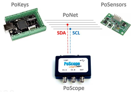
To see how I2C decoder works, you can use our PoKeys controller, connect it to PoSensors board and tap into the clock and data lines of i2c bus. They can be connected to any input of the logic analyzer port.
Clik here to view.
Decoding I2C protocol
To decode an I2C protocol with PoScopeMega1 open PoScope 4 application. With PoScopeMega1 set to digital mode and logic analyzer display open, click the Analyze button. In order to assure quality measurements, note that sampling rate has to higher than the signal frequency / bus clock rate. I2C is by default 100kBits/s (different speeds are supported) so we suggest you to setup sampling frequency to 500kS/s and set PoScope4 for capturing. After a second or so (so the buffers will be full) press Analyze button to switch to analyze.
Use the overview yellow selector and mouse scroller to select part of data for analysis and decoding. Pin that has most dense pulses is usually the clock. The second pin is data. You can also rename Pin by double-clicking its name.
Clik here to view.

I2C decoder clock (SCL) and data (SDA) lines
To start decoding I2C protocol, click the + button on the I2C pane under Decoders tab to add I2c decoder.
Clik here to view.

Adding I2C decoder
If you name your pins as I2C standard names (SCL, SDA) the decoder settings window will automatically recognize lines and use them for decoding otherwise you have to manually select pins for data sources.
Clik here to view.

I2C Settings window
Clik here to view.

Right panel with I2C decoder
Under the View, you can select how you want to display decoded data on the signal line:
- HEX – show hexadecimal value ,
- DEC – show decimal value,
- CHAR – show ASCII char
- BIN – show binary representation of the value.
There are available also some other combinations such as HEX & CHAR and DEC & CHAR. All decoded data will be visualized on the data signal in chart. Additional signal measurements can be shown in the right side panel or as a hint when you hover the mouse cursor over the decoded I2C data. If you hover your mouse over the decoded item, hint will show its full content and description if available.
Clik here to view.

Decoded I2C data in Logic analyzer display
I2C decoded data consists of:
- The start bit,
- Master read initialization,
- The address master wants to read from/write to,
- The acknowledge bit,
- The transferred data and
- The stop bit.
There is short video to explain how to decode I2C protocol with PoScope4 and PoScopeMega1.
This tutorial explained and demonstrated how easy is decoding of I2C protocol with PoScopeMega1 logic analyzer. If you are interested in PoScopeMega1 logic analyzer you can read more about it here.
The post Decoding I2C protocol with PoScopeMega1 appeared first on PoBlog™.